Crystal controlled 147.460 MHz FM transmitter The XFM1 transmitter is a crystal controlled tone modulated FM transmitter designed for model rockets but suitable for wildlife, balloons and many other applications requiring a small, frequency stable FM transmitter. Use this transmitter with a scanner or 2 meter amateur radio receiver. Transmitter ground range is approximately 400 yards (5 feet above ground) . Field tests were done with a ICOM IC-W32A transceiver with 0.16 micro volts of receiver sensitivity through the standard 8 inch antenna. Air to ground transmissions can improve range significantly as will a directional high gain antenna or a more sensitive receiver.General Specifications:
Frequency: 147.455 to 147.460
Mode: FM
Size: 2 .75 "x 0.5"
Weight: 8 grams (.3 oz) including battery
Range (ground): 400 yards with counterpoise
Frequency control: Crystal
Battery life: 3 days (two CR1632 batteries in series)
Receiver Type/requirements: FM, 144.455 - 147.460 MHz., 0.16microvolts sensitivity or better
Receiver Antenna: directional antenna recommended but not required.
Other: Knowledge of radio direction findingTRANSMITTER
The transmitter is a crystal controlled 147.460 MHz FM transmitter. The transmitter is tone modulated by a 12F675 microprocessor approximately every two seconds. A Morse code call sign ID is transmitted approximately every 30 seconds. If a call sign has not been specified it will transmit “XFM1”. The transmitter is turned off between tone bursts which greatly extends the battery life. The circuit is designed to use a low cost “computer crystal” 49.39 Mhz (3rd over tone), However, custom crystals can be used if other frequencies are desired. If other frequencies are desired a 3rd overtone series crystal can be ordered from a crystal manufacture. Microprocessor
The transmitter is controlled by a program running border=0>

Directional Beam antenna:A “beam” or “Yagi” antenna is probably the simplest and best all around choice for a directional antenna. A simple 3 element antenna can be built for about $10.00 using common materials. The sensitivity pattern shown below is when both the transmitter and receiving antenna is polarized vertically (the elements are pointing up and down). If the antenna of the transmitter are not vertical then the pattern will be different unless the receiving antenna is orientated to match the transmitter antenna. Since the transmitter antenna’s orientation is not always known some experimentation must be done with the receiving antenna. (Note that the patterns are not always as shown. They can vary depending border=0>
 Receivers To achieve adequate performance you will need a receiver with at least 0.16 micro volts of sensitivity. Most 2-meter Amateur (ham) radios are at least this sensitivity. Scanners may or may not be sensitivity enough.
Component Side View

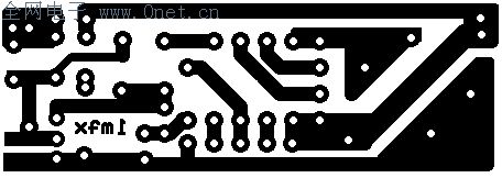
reversed foil side

2" x 0.65"
foil side
Transmitter parts Resistors Value Part number Supplier Comments R1 10K 1/8 watt 299-10K Mouser R2 100K 1/8 watt 299-100K Mouser Capacitors C1 .001uF 21RX510 Mouser C2 22pF 21RD722 Mouser C3 15pF 80-C315C150J1G Mouser two C3 (15pF caps) may be needed (see text) Semiconductors Q1 NTE107 526-NTE107 Mouser Q2 NTE108 526-NTE108 Mouser Crystal xtal 147.460 815-ABLS-49.152-B2 Mouser 49.152MHZ 3rd overtone crystal Inductors L1 0.68 uH 434-22-R68 Mouser L2 4 turns #22 magnet wire tightly wound on 1/8"dia. 278-1345B Radio Shack Enamel-coated magnet wire Miscellaneous Battery CR1632 or BR1632 658-BR1632 Mouser PCB See foil pattern antenna & Counterpoise 12 inch #20 to #24 solid conductor wire Just about any type of “hook-up” or phone wire J1 Jumper wire Use trimmed off lead source codetele147_1.asm |
