msd1819a-rt1 msd1819a-st1
5
motorola small–signal 晶体管, fets 和 二极管 设备 数据
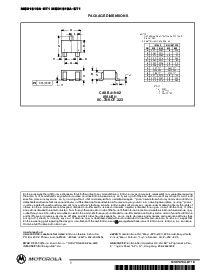
焊盘 stencil 指导原则
较早的 至放置 表面 挂载 组件 面向 一个 打印
电路板, 焊盘 paste 必须 是 应用 至 这 焊盘. 一个
焊盘stencil 是 必需的 至screen 这 最佳的 数量 的
焊盘paste 面向 这 footprint. 这 stencil 是 制造 的 黄铜
或者stainless steel 和 一个 典型 厚度 的 0.008 英寸.
这stencil opening 大小为 这 表面 挂载 包装
应当是 这 一样 作 这 垫子 大小 在 这 打印 电路
板, i.e., 一个 1:1 registration.
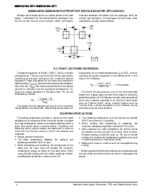
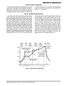
典型 焊盘 加热 profile
为任何 给 电路 板, 那里 将 是 一个 组 的 控制
settings那 将 给 这 desired 热温 模式. 这 运行器
必须set temperatures for several heating zones, 一个nd 一个
图示为 belt 速. taken 一起, 这些 控制 settings
制造向上 一个 加热 “profile” 为 那particular 电路 板.
Onm一个chines c在trolledby 一个 computer, the computer
remembers这些 profiles 从 一个 运行 session 至 这
next.图示 8 显示 一个 典型 加热 profile 为 使用 当
焊接一个 表面 挂载 设备至 一个 打印 电路 板.
这个profile 将 相异 among焊接 系统 但是 它 是 一个 好的
开始要点. factors 那 能 affect 这 profile 包含 这
typeof soldering system in use, density 一个nd types of
组件 在这 板, 类型 的 焊盘 使用, 和 这 类型
的板 或者 基质 材料 正在 使用. 这个 profile 显示
温度相比 时间.这 线条 在 这 图表 显示 这
真实的温度 那 might 是 experienced 在 这表面
的一个 test board 一个t or near 一个 central solder joint. the two
profiles是 为基础 在 一个 高 密度 和 一个 低 密度 板.
这Vitronics smd310convection/infrared 软熔焊接 焊接
系统是 使用 至 发生 这个 profile. 这 类型 的 焊盘
使用w一个s 62/36/2 tin lead silver w它h 一个 melting point
在177–189
°
c. 当 这个 类型 的 furnace 是 使用 为
焊盘软熔焊接 工作, 这 电路 boards 和 焊盘 joints tend至
热温 第一.这 组件 在 这 板 是 然后 heated 用
传导.这 电路 板, 因为 它 有一个 大 表面
范围,一个bsorbs the thermal energym或者e efficiently, then
distributes这个活力 至 这 组件. 因为 的 这个
效应,the main body of 一个 component m一个y be up to 30
degrees cooler 比 这 调整 焊盘 joints.
步伐 1
PREHEAT
zone 1
“RAMP”
步伐 2
VENT
“SOAK”
步伐 3
加热
zones 2 &放大; 5
“RAMP”
步伐 4
加热
zones 3 &放大; 6
“SOAK”
步伐 5
加热
zones 4 &放大; 7
“SPIKE”
步伐 6
VENT
步伐 7
冷却
200
°
C
150
°
C
100
°
C
50
°
C
时间 (3 至 7 分钟 总的)
T
最大值
焊盘 是 liquid 为
40 至 80 秒
(取决于 在
mass 的 组装)
205
°
至 219
°
C
顶峰 在
焊盘 joint
desired 曲线 为 低
mass assemblies
100
°
C
150
°
C
160
°
C
140
°
C
图示 8. 典型 焊盘 加热 profile
desired 曲线 为 高
mass assemblies
170
°
C